


--->내압시험기


Description
applicable to low-capacitance units under test.
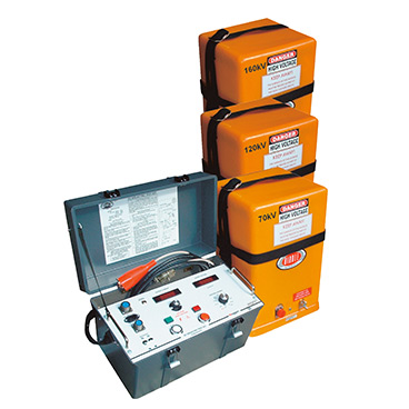
160 kV) provide the most dependable, portable dc highvoltage sources for checking the quality of electrical power cables, motors, switchgear, insulators, transformers and capacitors. Each portable set (heaviest is 73 lb, 32.8 kg) is comprised of two separate modules:
Control Module
This module allows the operator to switch-select the appropriate current output range, adjust the output level and monitor both the applied voltage and leakage current at a safe distance from the high voltage being delivered to the load under test. No voltage higher than input ac power is present in the control module.
High-Voltage Module
An air-insulated design receives its instructions from the control unit. It generates the dc high voltage that is delivered to the load under test.
Although a different control module is used with each of the three models, they are all the same size and weight.
Each high-voltage module is a different size and weight to accommodate the rated output voltage.
Applications
The dc dielectric test sets are used to make proof tests and insulation tests on electrical power cables, motors, switchgear, insulators, transformers and capacitors.
Both types of tests are performed by applying controlled high voltages to the unit under test at or above insulation system operating level. Measuring the leakage current helps determine the unit under test’s ability to withstand overvoltages such as lightning strikes and switching surges.
The three models described cover a range of output voltages that meet the most commonly specified ratings in 5-kV to 69-kV class cable. All are suitable for testing power cable, switchgear and rotating machinery in accordance with IEEE, IPCEA, NEMA and ANSI uidelines.
Proof Test
Proof testing is used for acceptance testing of newly installed cable and maintenance testing of aged and/or repaired cable. For the proof test, the unit under test will either withstand the test voltage or it will “break down,” providing the user with a “go/no-go” answer.
Insulation Resistance Tests
To make appropriate tests on healthy insulation, the test instrument must have microampere sensitivity. Insulation resistance can be measured in at least three different ways:
The insulation resistance test is often referred to as a “spot check,” and is performed by applying a predetermined voltage to the unit under test, holding it until the apparent leakage current becomes stable and recording the readings with adjustments for temperature. This test is especially applicable to low-capacitance units under test.
Time-varying tests such as the polarization index test (PI type of test is only useful for high-capacitance samples.
To perform this test, a predetermined test voltage is applied to the unit under test and readings are taken at 1 minute and 10 minutes. The resulting ratio is analyzed to determine
insulation quality. This type of test is especially appropriate for high-capacitance samples.
The step-voltage test is independent of temperature effects and saves time. To perform this test, the output voltage is increased in even steps at regular intervals over a fixed period of time. As long as the resistance of the unit under test increases with time, it has high-quality insulation.
This type of test is only useful for high-capacitance samples.
Specifications
Accuracy: ±2% of full scale range
Nominal 120 Vac, 50/60 Hz
For 220/240 Vac, 50/60-Hz operation, add –47 to Cat. No.
Please note that specifications for the –47 models differ as
follows:
Output Current: 220/240 Vac
120 kV Models: 5 mA for 5 min; 2 mA continuous
160 kV Models: 5 mA for 5 min; 1.5 mA continuous
When using external 240/120-volt step-down voltage transformers,
the ratings may be used as given for 120 volt input.
Weight: Add approx 2 lb (1 kg) for –47 control unit.
Ammeter (Digital Models)
Ranges:
0 to 19.9 μA
0 to 199 μA
0 to 1.99 mA
0 to 5 mA
Resolution: To 0.1 μA on lowest range
Accuracy: ±2% of reading + 1 digit
Ammeter (Analog Models)
Ranges:
0 to 5 μA
0 to 50 μA
0 to 500 mA
0 to 5 mA
Resolution: To 0.1 μA on lowest range
Accuracy: ±2% of full scale range
Voltmeter (Digital Models)
Resolution: To 100 V over entire range
Accuracy: ±(2% of reading + 100 V)
Voltmeter (Analog Models)
Resolution — Dual Range:
35 kV/70 kV: 2.5% full scale
60 kV/120 kV: 1.6% full scale
80 kV/160 kV: 2.5% full scale
Accuracy: ±2% of full scale range
Ripple
160 kV: 39 H x 12 W x 12 D in. (1000 H x 305 W x 305 D mm)
Temperature Range
Operating: -20 to +130° F (-30 to +55° C)
Storage: -40 to +150° F (-40 to +65° C)
Relative Humidity Range
Operating: 0 to 90% noncondensing
Storage: 0 to 95% noncondensing
Dimensions
Control Unit (all models)
20 H x 12 W x 12.5 D in.
(510 H x 305 W x 318 D mm)
High Voltage Unit
70 kV: 20 H x 12 W x 12 D in. (510 H x 305 W x 305 D mm)
120 kV: 29 H x 12 W x 12 D in. (740 H x 305 W x 305 D mm)
160 kV: 39 H x 12 W x 12 D in. (1000 H x 305 W x 305 D mm)
Weight
120 and 160 kV Models: 9 lb (4 kg)
23 lb (10.5 kg)
High-Voltage Unit
70 kV: 44 lb (20 kg)
120 kV: 65 lb (30 kg)
160 kV: 73 lb (33 kg)
Cables (including carrying bag)
70 kV Models: 7 lb (3 kg)
120 and 160 kV Models: 9 lb (4 kg)
세부사항은 기술자료실 참조
울산광역시 남구 정동로 11-1(삼산동 1600-7) | 전화번호 : 052-272-8461~2 | 팩스번호 : 052-272-8463
COPYRIGHT © www.dongasystem.co.kr. All rights reseved