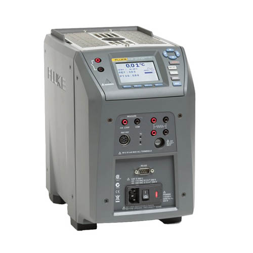
9142/9143/9144 현장 계측웰
대형 현장 용도를 위한 소형 드라이웰
신형 914X 시리즈 현장 계측웰들은 뛰어난 성능을 산업용 프로세스 환경에 접목 시켜 휴대성, 속도, 기능을 최대화하면서 계측성능의 타협은 최소화합니다.
현장계측웰은 다재다능하며 놀라울 만큼 쉽습니다. 가볍고 작으며 온도 set point를 빠르게 도달하면서도 안정적이고 균일하며 정확합니다. 이 산업용 루프 교정기들은 전송기 루프 교정, 비교 교정, 혹은 열전대 센서의 단순 점검에 적합합니다. "프로세스" 옵션기능으로 현장에 추가 장비를 가지고 가지 않아도 되며, 내장된 2채널 판독 옵션은 24볼트 루프 파워를 가지고 저항, 전압 그리고 4-20mA 전류을 읽어냅니다. 또한 온-보드 의 문서 참고 및 자동화를 지원하며 3가지 모델 (9142, 9143, 9144—각각의 “프로세스” 옵션 포함)이 결합되어 –25 °C에서 660 °C까지 넓은 범위의 온도를 커버합니다.
산업 현장을 위한 고성능
현장 계측웰들은 산업 프로세스 환경에 맞게 설계되었습니다. 8.2 kg (18 lb)보다 가벼운 소형 사이즈로 운송이 쉽고 속도에 최적화 되었습니다. 현장 계측웰은 –25 °C에서 15분간 냉각하고 660 °C에서 15분간 열에 노출시킬 수 있습니다.
또한 현장 환경 조건들은 불안정하여 넓은 온도 변화폭을 갖습니다. 각 현장 계측웰은 경사 온도 보정 (특허 출원)이 내장되어 불안정한 환경에서도 안정적인 성능을 내도록 제어 특성을 조정합니다. 모든 사양은 13 °C에서 33 °C의 외부환경 범위를 보장합니다.
경량, 휴대용, 고속Cool to –25 °C in 15 minutes and heat to 660°C in 15 minutesBuilt-in two-channel readout for PRT, RTD, thermocouple, 4-20 mA currentTrue reference thermometry with accuracy to ±0.01 °C온-보드 자동화 및 문서정확도, 안정도, 균일성, 부하에서의 Metrology 성능많은 양의 업무 부하와 빈번한 사용을 위한 내장 기능
Whether you need to calibrate 4-20 mA transmitters or a simple thermostatic switch, a Field Metrology Well is the right tool for the job. With three models covering the range of –25 °C to 660 °C, this family of Metrology Wells calibrates a wide range of sensor types. The optional process version (models 914X-X-P) provides a built-in two-channel thermometer readout that measures PRTs, RTDs, thermocouples, and 4-20 mA transmitters which includes the 24 V loop supply to power the transmitter.
각 프로세스 버전은 ITS-90 기준 PRT를 수용합니다. The built-in readout accuracy ranges from ± 0.01 °C to ± 0.07 °C depending on the measured temperature. Reference PRT for Field Metrology Well은 센서 하우징 내부의 메모리 칩에 개별 교정 상수를 내장하여 센서들을 교환할 수 있습니다. The second channel is user-selectable for 2-, 3-, or 4-wire RTDs, thermocouples, or 4-20 mA transmitters. For comparison calibration, don’t hassle with carrying multiple instruments to the field. Field Metrology Well은 이 모든 것을 하나의 장비로 이루어냅니다.
전통적으로 온도 전송기의 교정은 전자 측정 장치로 수행되었으며, 센서는 교정되지 않은 상태로 남아있었습니다. Studies have shown, however, that typically 75 % of the error in the transmitter system (transmitter electronics and temperature sensor) is in the sensing element. 따라서 전자 장치와 센서를 포함한 전체 루프를 교정하는 것이 중요합니다.
Field Metrology Well의 프로세스 옵션은 전송기 루프 루프 교정을 쉽게 도와드립니다. 전송 센서는 기준 PRT와 Well에 넣어지고, 자ㅓㄴ자 전송기는 장비의 전면 패널에 연결됩니다. With 24 V loop power, you are able to power and measure the transmitter current while sourcing and measuring temperature in the Field Metrology Well. 이로써 하나의 독립 교정 툴을 이용해 여러가지 다양한 툴의 데이터를 측정할 수 있습니다.
모든 Field Metrology Well은 자동 혹은 수동 설정의 두 가지 자동 thermostatic switch 테스트 절차를 제공합니다. 자동 설정은 공칭 스위치온도만 입력하면 됩니다. 입력만 하면 3 사이클 교정 절차를 수행하고 데드 밴드 (dead band) 온도를 디스플레이에 표시하게 됩니다. 램프 속도를 원하는 대로 정하거나 추가 사이클을 수행하고 싶은 경우, 수동 설정을 통해 프로그램을 원하는 대로 설정하고 수행할 수 있습니다. 두 방법 모두 빠르고 쉬우며 온도 스위치 테스트가 보다 즐거워 집니다.
높은 정확도 측정을 위한 metrology 성능
기존 dry well들과는 달리 Field Metrology Well은 속도와 휴대성을 최대화줌과 동시에 EA에서 제시하는 다음 여섯 가지 핵심 metrology 성능 기준을 철저히 준수합니다: 정확도, 안정도, 축 (수직) 균일성, 방사 (well간), 균일성, 부하, 이력도. 이것들은 모든 측정 용도상에서 정확한 측정하기 위해 중요한 기준들입니다. Field Metrology Well 디스플레이는 고품질 소급가능하며 인증된 PRT에 의해 교정됩니다. 각 장치 (process 및 비 프로세스 버전)은 IEC-17025 NVLAP 인증 교정 인증서와 함께 제공되며, 이는 온도 경사, 부하 효과, 이력도를 고려하는 견고 불확도 분석으로 뒷받침 되었습니다. The 9142 and 9143 have a display accuracy of ± 0.2 °C over their full range, and the 9144 display accuracy ranges from ± 0.35 °C at 420 °C to ± 0.5 °C at ± 660 °C. Each calibration is backed with a 4:1 test uncertainty ratio.
 New control technology guarantees excellent performance in extreme environmental conditions. The 9142 is stable to ± 0.01 °C over its full range and the mid-range 9143 is stable from ± 0.02 °C at 33 °C and ± 0.03 °C at 350 °C. Even at 660 °C, the 9144 is stable to ± 0.05 °C. But this is not all! Thermal block characteristics provide radial (well-towell) uniformity performance to ± 0.01 °C. Dual-zone control helps these tools achieve axial uniformity to ± 0.05 °C at 40 mm (1.6 in).
자동화와 문서화는 각 장치를 턴키 솔루션으로 만듭니다
이로 인해 현장에 적합한 특성, 인증된 metrology 성능, 내장 2채널 온도계를 가졌으며 자동화된 정밀 교정 장비를 얻을 수 있습니다. 더 이상 무엇을 원하십니까? 이 모든 것을 자동화하고 문서 기록하는 턴키 솔루션은 어떠십니까?
Field Metrology Well의 프로세스 버전은 내장 비휘발성 메모리 덕분에 최대 20개 테스트의 문서기록을 담을 수 있습니다. 각 테스트에 고유 알파뉴메릭(영어와 숫자의 혼합 표기) ID가 부여될 수 있고 블록 온도, 기준 온도, UUT 수치, 에러, 데이터와 시간을 기록할 수 있습니다. 각 테스트는 전면 패널로 살펴볼 수 있으며, 각제품과 함께 제공되는 모델 9930 Interface-It 소프트웨어로 내보낼 수 있습니다. Interface-it allows you to pull the raw data into a calibration report or an ASCII file.
동작은 매우 쉽습니다.
You’ll find Field Metrology Wells intuitive and easy to use. Each unit is equipped with a large, easy-to-read LCD display, function keys, and menu navigation buttons. Its “SET PT.” button makes it straightforward and simple to set the block temperature. Each product has a stability indicator that visually and audibly tells you the Field Metrology Wells is stable to the selectable criteria. Each unit offers preprogrammed calibration routines stored in memory for easy recall, and all inputs are easily accessible via the front panel of the instrument. Never buy a temperature calibration tool from a company that only dabbles in metrology (or doesn’t even know the word). Metrology Wells from Fluke are designed and manufactured by the same people who equip the calibration laboratories of the world’s leading temperature scientists. These are the people around the world who decide what a Kelvin is! We know a thing or two more about temperature calibration than the vast majority of the world’s dry-well suppliers. Yes, they can connect a piece of metal to a heater and a control sensor. But we invite you to compare all our specs against the few that they publish. (And by the way, we meet our specs!).
| 기본 단위 사양 |
| Temperature Range at 23 °C | | 9142 | –25 °C to 150 °C (–13 °F to 302 °F) | | 9143 | 33 °C to 350 °C (91 °F to 662 °F) | | 9144 | 50 °C to 660 °C (122 °F to 1220 °F) |
|
| Display Accuracy | | 9142 | ± 0.2 °C Full Range | | 9143 | ± 0.2 °C Full Range | | 9144 | ± 0.35 °C at 50 °C | | | ± 0.35 °C at 420 °C | | | ± 0.5 °C at 660 °C |
|
| 안정성 | | 9142 | ± 0.01 °C Full Range | | 9143 | ± 0.02 °C at 33 °C | | | ± 0.02 °C at 200 °C | | | ± 0.03 °C at 350 °C | | 9144 | ± 0.03 °C at 50 °C | | | ± 0.04 °C at 420 °C | | | ± 0.05 °C at 660 °C |
|
| Axial Uniformity at 40 mm (1.6 in) | | 9142 | ± 0.05 °C Full Range | | 9143 | ± 0.04 °C at 33 °C | | | ± 0.1 °C at 200 °C | | | ± 0.2 °C at 350 °C | | 9144 | ± 0.05 °C at 50 °C | | | ± 0.35 °C at 420 °C | | | ± 0.5 °C at 660 °C |
|
| 방사 균일성 | | 9142 | ± 0.01 °C Full Range | | 9143 | ± 0.01 °C at 33 °C | | | ± 0.015 °C at 200 °C | | | ± 0.02 °C at 350 °C | | 9144 | ± 0.02 °C at 50 °C | | | ± 0.05 °C at 420 °C | | | ± 0.10 °C at 660 °C |
|
| Loading Effect (with a 6.35 mm reference probe and three 6.35 mm probes) | | 9142 | ± 0.006 °C Full Range | | 9143 | ± 0.015 °C Full Range | | 9144 | ± 0.015 °C at 50 °C | | | ± 0.025 °C at 420 °C | | | ± 0.035 °C at 660 °C |
|
| Hysteresis | | 9142 | 0.025 | | 9143 | 0.03 | | 9144 | 0.1 |
|
| 동작 환경 | | | 0 °C to 50 °C, 0 % to 90 % RH (non-condensing) |
|
| 환경 조건 (온도 범위를 제외한 모든 사양) | |
| 담금 (Well) 깊이 | |
| 장착물 OD | | 9142 | 30 mm (1.18 in) | | 9143 | 25.3 mm (1.00 in) | | 9144 | 24.4 mm (0.96 in) |
|
| Heating Time | | 9142 | 16 min: 23 °C to 140 °C | | | 23 min: 23 °C to 150 °C | | | 25 min: –25 °C to 150 °C | | 9143 | 5 min: 33 °C to 350 °C | | 9144 | 15 min: 50 °C to 660 °C |
|
| Cooling Time | | 9142 | 15 min: 23 °C to –25 °C | | | 25 min: 150 °C to –23 °C | | 9143 | 32 min: 350 °C to 33 °C | | | 14 min: 350 °C to 100 °C | | 9144 | 35 min: 660 °C to 50 °C | | | 25 min: 660 °C to 100 °C |
|
| 분해능 | |
| 디스플레이 | | | LCD, °C or °F user-selectable |
|
| Size (H x W x D) | | | 290 mm x 185 mm x 295 mm (11.4 x 7.3 x 11.6 인치) |
|
| 중량 | | 9142 | 8.16 kg (18 lb) | | 9143 | 7.3 kg (16 lb) | | 9144 | 7.7 kg (17 lb) |
|
| Power Requirements | | 9142 | 100 V to 115 V (± 10 %) 50/60 Hz, 635 W 230 V (± 10 %) 50/60 Hz, 575 W | | 9143 9144 | 100 V to 115 V (± 10 %), 50/60 Hz, 1400 W 230 V (± 10 %), 50/60 Hz, 1800 W |
|
| Computer Interface | | | RS-232 and 9930 Interface-it control software included |
|
| -P 사양 |
| Built-in Reference Thermometer Readout Accuracy (4-Wire Reference Probe)† | | | ± 0.010 °C at -25 °C
± 0.015 °C at 0 °C
± 0.020 °C at 50 °C
± 0.025 °C at 150 °C
± 0.030 °C at 200 °C
± 0.040 °C at 350 °C
± 0.050 °C at 420 °C
± 0.070 °C at 660 °C |
|
| 기준 저항 범위 | |
| Reference Resistance Accuracy‡ | | | 0 ohms to 42 ohms: ±0.0025 ohms 42 ohms to
400 ohms: ±60 ppm of reading |
|
| 기준 특성 | |
| 기준 측정 능력 | |
| 기준 프로브 연결 | | | Infocon Technology 6-pin Din |
|
| 내장 RTD Thermometer readout 정확도 | | | NI-120: ± 0.015 °C at 0 °C | | | PT-100 (385): ± 0.02 °C at 0 °C | | | PT-100 (3926): ± 0.02 °C at 0 °C | | | PT-100 (JIS): ± 0.02 °C at 0 °C |
|
| RTD 저항 범위 | |
| RTD Resistance Accuracy‡ | | | 0 ohms to 25 ohms: ±0.002 ohms | | | 25 ohms to 400 ohms: ±80 ppm of reading |
|
| RTD 특성 | | | PT-100 (385), (JIS), (3926), NI-120, 저항 |
|
| RTD 측정 기능 | | | 4-wire RTD (2-, 3-wire RTD w 점퍼만) |
|
| RTD 연결 | |
| 내장 TC Thermometer readout 정확도 | | | Type J: ± 0.7 °C at 660 °C
Type K: ± 0.8 °C at 660 °C
Type T: ± 0.8 °C at 400 °C
Type E: ± 0.7 °C at 660 °C
Type R: ± 1.4 °C at 660 °C
Type S: ± 1.5 °C at 660 °C
Type M: ± 1.4 °C at 660 °C
Type L: ± 0.7 °C at 660 °C
Type U: ± 0.75 °C at 600 °C
Type N: ± 0.9 °C at 660 °C
Type C: ± 1.1 °C at 660 °C |
|
| TC Millivolt 범위 | |
| 전압 정확도 | | | 0.025% of reading + 0.01 mV |
|
| 내부 냉접점 보상 정확도 | | | ± 0.35 °C (ambient of 13 °C to 33 °C) |
|
| TC 연결 | |
| 내장 mA 판독 정확도 | |
| mA 범위 | | | Cal 4-22 mA, Spec 4-24 mA |
|
| mA 연결 | |
| Loop Power 기능 | |
| Built-in Electronics Temperature Coefficient (0 °C to 13 °C, 33 °C to 50 °C) | | | ± 0.005 % of range per °C |
|
†온도 범위는 read out에 연결된 기준 프로브의 제한을 받습니다. 내장 기준 thermometer readout의 정확도는 센서 프로브 정확도를 포함하지 않습니다. It does not include the probe uncertainty or probe characterization errors.
‡ Measurement accuracy specifications apply within the operating range and assume 4-wires for PRTs. 3 와이어 RTD는 측정 정확도에 0.05옴과 리드 와이어간 저항의 최대 차이를 더합니다.
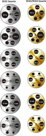
위의 모델명들에서 X는 원하는 장착물에 맞게 A, B, C, D, E 혹은 F로 교체합니다. 장착물 표와 삽화는 아래를 참고하십시오.